Intro
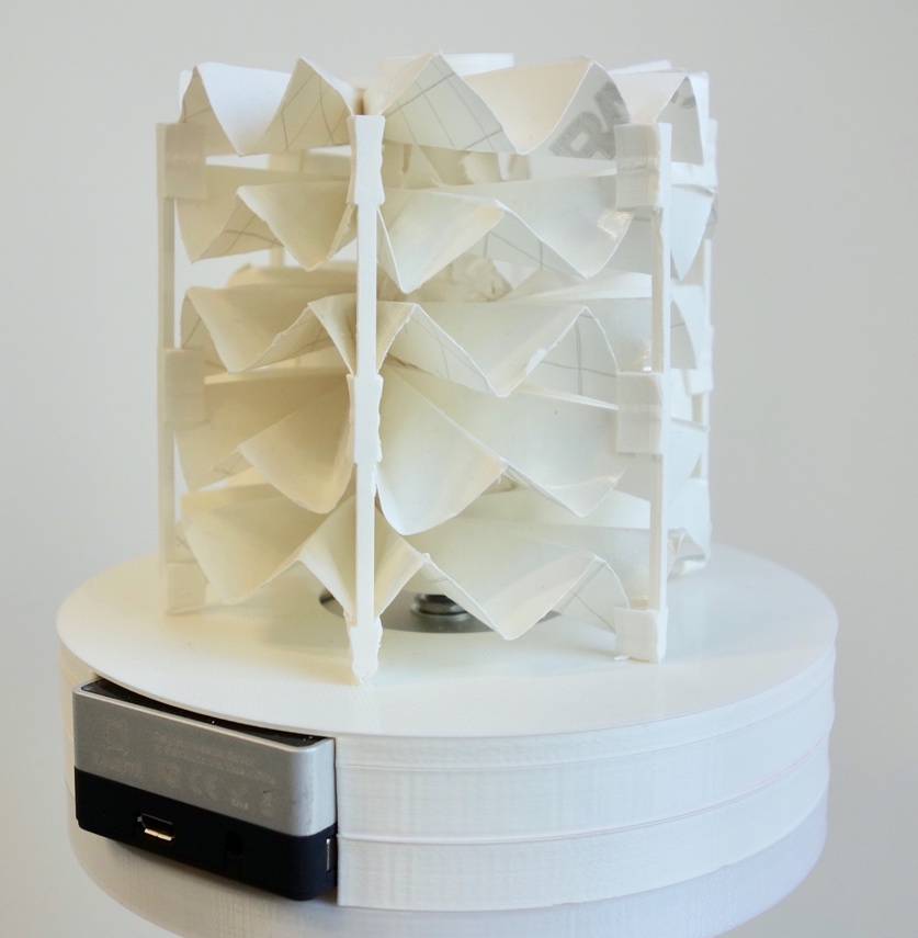
ExpanDial is a shape-changing Dial, which can change its height and width. It's built to investigate future applications and usability of such shape-changing interfaces. For details about the project, check out our publication at ACM.
Materials
To build an ExpanDial, you need below Materials.
· Six linear motors (Firgelli L12-50-100-6-R) and a controller for them
· One Palette display and one Palette knob
· Twelve bolts and nuts
· Dial
o Five copies of the origami pattern, folded. We used the back side of vinyl stickers and a vinyl cutter.
o Six origami connectors to connect the copies of the origami pattern.
o Dial rod and a cover for it.
· Dial base
o One 3D print of the bottom layer of the base
o Two 3D prints of the middle layer of the base
o One 3D print of the top layer of the base
·
Accessories for motors
o Six 3D prints of motor-case connectors
o Three 3D prints of a pushing wall
· Case
o Laser cut of 3mm flexi glass based on the case plan
How to Build
Dial and dial base
1. Take out the central circle of the origami patterns, make it hollow.
2. Insert the patterns to the dial rod and connect the origami patterns with the origami connectors at every second mountain or valley (depending on the layer. Look at the figure above).
3. Close the rod with the cover.
4. Connect the Palette display and knob.
5. Place the display and knob on the flat side of the bottom layer of the dial base. Linear motors will be connected on the other side.
6. Add the two middle layers and the top layer on the bottom layer.
7. Connect the dial rod to the Palette knob.
Case
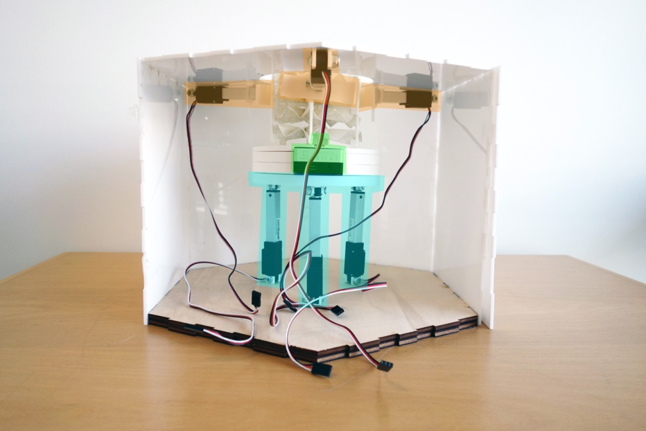
1. Combine the two pieces of the case bottom. The case bottom pieces have hexagon shape and no circular hole on them. The piece with three holes to go below, and the piece with six holes go above.
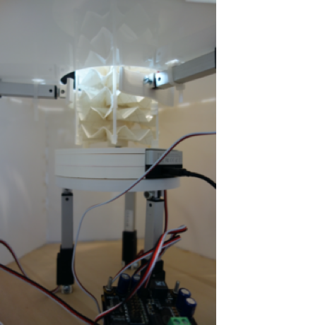
2. Add three motor connectors from the below piece.
3. Fix three motors on the connectors using bolts and nuts. In this way, the motors should be fixed to the case bottom.
4. Connect the case base to the motors using bolts and nuts.
5. Connect
the rest three motors to the pushing walls using bolts and nuts.
6. Connect the motors to the case top piece using the rest three motor connectors, bolts and nuts. Be aware of the direction of the wall. The short side should face the case top piece.
7. Connect the motors to a controller.
8. Connect the controller and the Palette display to a PC.